ZN085 ABRITES V850/RH850 TIPS AND TRICKS
Before we begin I also wanted to take the time to thank the guys at Feedspot who absolutely independently ranked the Abrites blog at number 7 on their Top 15 Automotive Diagnostic Blogs List!
In today’s edition of the Abrites blog we wanted to do something more than the usual for you guys, we wanted to share some additional information which will help your work with the ZN085 programmer. We teamed up with the guys from our development team who work on the V 850 and RH 850 programmer to give you a series of tips and tricks about the operation of the programmer. As I mentioned last week, we are working on simplifying the processes of reading by reducing the number of components to be removed (by at least 30% with the next update). This is done in order to reduce the options for failure and basically take any risk out of your work with the Renesas (NEC) equipped modules. Until we manage to release this revision here is how we work.
I. Power supply.
The ZN085 comes with a designated power supply. In theory this power supply is not an absolute necessity when reading, but we strongly recommend you use it. It helps stabilize the current supply and improves the stability of the reading operations. When it comes to writing the power, supply is a must.
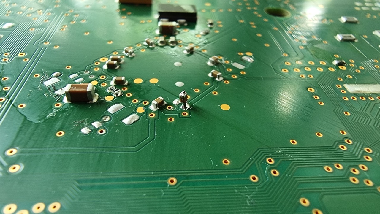
II. Don’t blow, just warm up.
Do not remove capacitors with the help of a heat gun, you risk a lot, just use your soldering iron. Holding the heat gun over the PCB can delaminate tracks, causing issues to it. If the flow is too high, you can blow an element away and lose it.
III. Do not extend the cables.
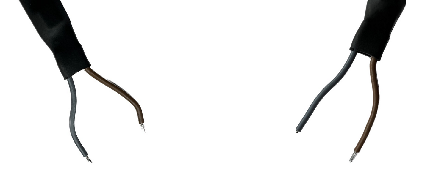
Out of the box the cables are long enough. Longer cables will cause disturbances in the force, and they will be a reason for trouble sooner, rather than later, they are long enough. In fact, you should shorten them as per the photo. We saw people extending the supplied cables which caused issues.
IV. Thick double-sided tape.
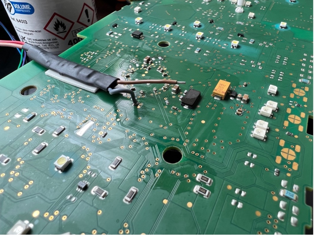
Protect your PCB, please stop using painter’s tape as it will ruin any PCB when you least expect it.
V. Vertical cable placement.
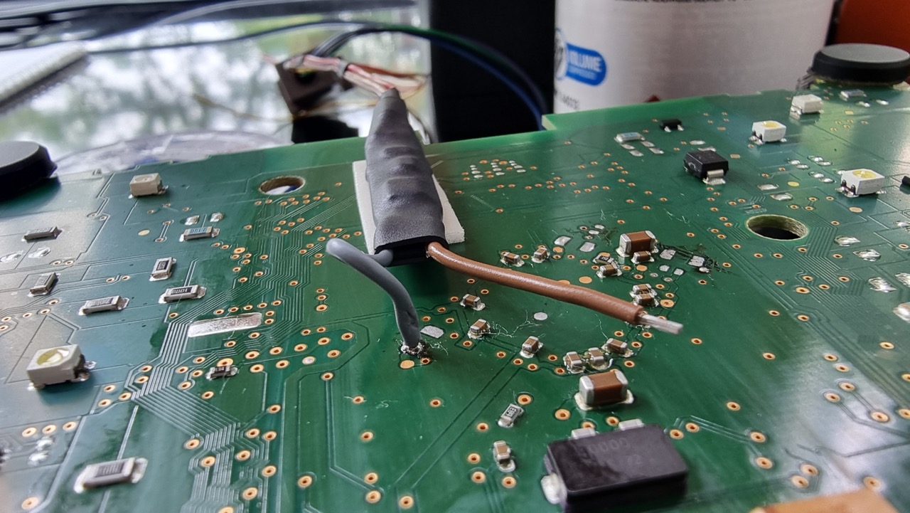
Go straight up from the soldering point on your PCB, this improves cable signal and minimizes the risk of soldering neighboring points on which is certain to cause trouble.
VI. Capacitor removal strategy.
Until we manage to make removing elements from the PCB a non-requirement, we are forcing you to remove capacitors. One thing the guys at the development department showed me but I could not take photos of was a strategy where they flooded the capacitors with flux on both sides which helps the capacitor loosen from its position (essentially turning it into a flux capacitor), after that using the soldering iron, they slightly pushed and warmed it from one side to the other slightly moving it from its position. This leaves the flux as a short so you have to clean up afterwards, but it will not damage the capacitor.

VII. Neatly organized.
If you are working on a PCB and you need to remove a component as small as hen’s tooth a good strategy is to leave it in its place afterwards by simply soldering it to one of the ends where it was placed.
This helps you not lose the components you have removed.
Not much more I can say – just try to be careful because one of the guys I spoke with last week was able to turn a dashboard into a stove by accidentally soldering more than needed. Please be careful.
Until Next week,
Alek
 Ricalibrazione quadri strumenti per veicoli
 Sblocco/reset batteria per veicoli Mercedes-Benz